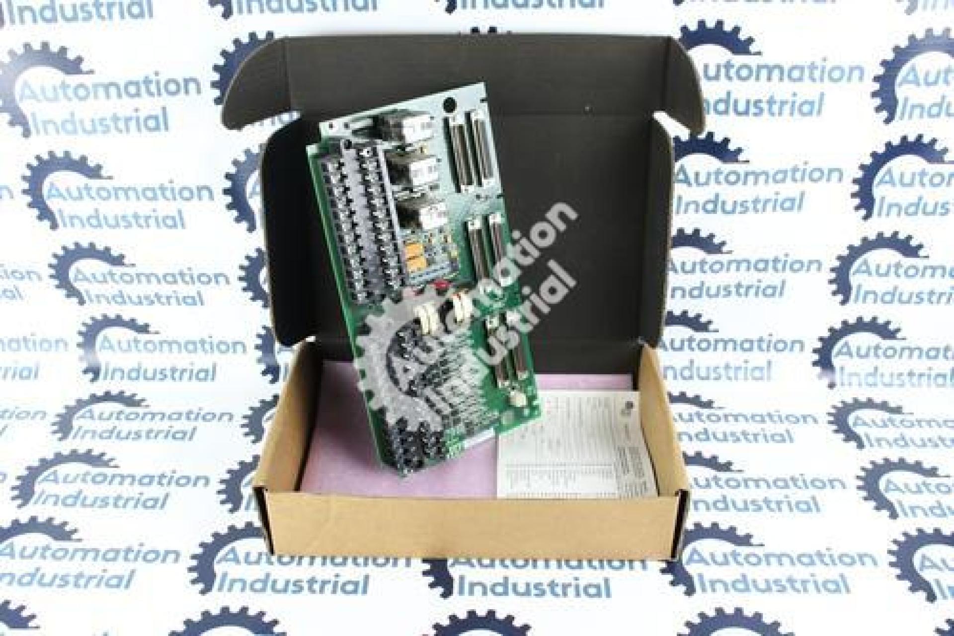
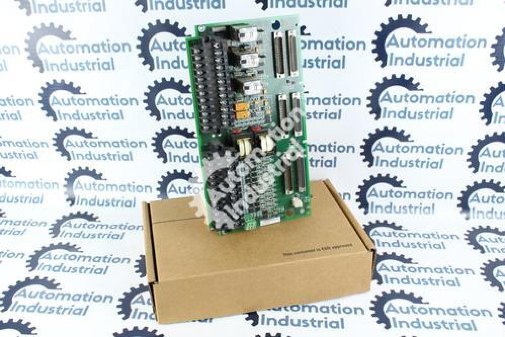
How the IS200TTURH1CCC Behaves in a TMR System
In a triple modular redundant (TMR) Mark VI installation, the IS200TTURH1CCC — a Turbine Terminal Board — fans its speed and voltage inputs out to all three control racks rather than feeding a single controller. Turbine speed pickups, generator and bus voltage from potential transformers, and shaft voltage/current signals all reach the R, S, and T channels, where they're voted before being allowed to influence the synchronizing permissive relays K25 and K25P. A third relay, K25A, provides an internal synch check, and all of them have to be satisfied before the board energizes the generator breaker coil (52G) at a nominal 125 V DC. An external synch check relay adds a further layer of protection in series with K25/K25P, and a 52G/a auxiliary contact on the physical breaker — not a relay copy — feeds actual closing-time data back to the control system.
As a terminal board, the TTUR is where all of this field wiring physically lands: two 24-terminal blocks (TB1, TB2) accept magnetic pickup, shaft sensor, PT, and breaker relay wiring up to #12 AWG, with jumpers JP1/JP2 configuring simplex or TMR relay-drive mode. The actual processing happens on a separate VME card, VTUR, in each Control Module, reached from the TTUR by cable through six connectors — JR1/JR5, JS1/JS5, JT1/JT5 — one pair per channel.
Voting Alarms vs. Real Board Failures
Because TMR systems vote three redundant channels against each other, a lot of what looks like a serious fault is actually a single bad input, not a board-wide failure:
- A voting disagreement between R, S, and T on speed is much more often a drifted magnetic pickup or a wiring problem on one channel than a failure of all three terminal boards at once.
- A synchronizing failure that won't clear should send you to the external synch check relay, the 52G/a feedback contact, PT wiring/fuses, and the JP1/JP2 jumper settings before you order a new board.
- A shaft voltage or current alarm almost always traces back to a grounding brush or bearing insulation issue on the shaft train itself, since this board only monitors that condition rather than causing it.
- Loose terminals on TB1/TB2 or a partially seated JR/JS/JT connector are common, easily fixed causes of intermittent faults that get mistaken for board failures.
Reading the IS200TTURH1CCC Part Number
IS200 is the platform prefix, TTUR the function code, and H1CCC the group and revision — H1C for the group/generation, CC for this specific revision. Order and quote the complete string; H1C and the H1B-series TTUR boards also stocked here are different hardware generations sharing the same basic function. Our GE Speedtronic Part Number Decoder covers how to parse a full IS200 string.
Related Boards
The TTUR's VME companion is VTUR, in the Control Module. The generator breaker trip circuit also runs through the TRPG terminal board (driven by VTUR) and, in the Backup Protection Module, the TREG terminal board (driven by VPRO). If your site also runs Mark V equipment, see our Mark V vs Mark VI: DS200 to IS200 guide and GE Mark V DS200 Boards Explained article. Browse the rest of the family in our GE Mark VI IS200 Boards collection or the wider GE Speedtronic Turbine Control Boards collection.
What to Include in Your Quote Request
- Full part number with suffix: IS200TTURH1CCC
- Revision from the label
- Photo of the ID label
- Turbine/generator model and unit ID
- Planned outage or urgent need
- Quantity
Request a Quote
This IS200TTURH1CCC is listed in used condition, clean and tested, with a 1-year warranty (see table below). We quote every order directly rather than publishing prices — submit a Request a Quote and expect a reply within 24 hours. We ship worldwide DDP, accept purchase orders, and support both planned outages and urgent breakdown needs.
General Information about the Product |
Part Number |
IS200TTURH1C Mark VI IS200 |
Description |
GE IS200TTURH1C IS200TTURH1CCC Turbine Terminal Board Mark VI |
Condition |
used Clean and Tested. With 1 Year Warranty. |